by Zack Goyetche, Electrical Engineer at Iris Automation

As an electrical engineer who is obsessed with creating the physical, I delightedly jumped at the opportunity to design and build hardware for Iris Automation when it presented itself one year ago.
This opportunity was unique in that I would single-handedly own everything under the umbrella of electronic hardware design, gaining a first-hand holistic understanding of what it takes to design and build electronics that are capable of meeting the demands of today’s problems.
In May of 2018 I found myself on a plane to Iris Automation’s headquarters in the Financial District of San Francisco. I would be on-boarding and meeting with the CTO to learn about the present state of Iris’ technology and the direction the hardware needed to go to support artificial intelligence on the edge.

Iris Automation is creating a vision and AI based sense-and-avoid technology that will give drones the ability to fly, what the FAA calls, “beyond visual line of sight.” To put it simply, Iris’ technology would eliminate the FAA’s requirement of a human observer maintaining a visual line of sight with the drone at all times. Solving this problem will provide immense value to society by allowing drones to be utilized for tasks that are too dangerous, dirty, or dull for humans to do.
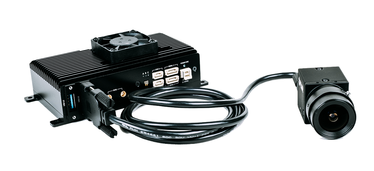
After spending two days in a meeting room white-boarding a rough plan of action, I set out to begin the hardware design for Iris’ compute module, later named ‘Casia’.

My first order of business was to create templates for schematics, stack-ups, bill-of-materials, fabrication drawings, and assembly drawings. These documents are the distilled result of all of the design efforts, containing all of the information required to manufacture and build the hardware.
“Organization will set you free.” — Alton Brown

It is important to get documentation right from the get-go, as playing catch up will undoubtedly result in mistakes that waste time, energy, and money. I have developed a keen appreciation for organization, as it is an excellent weapon to combat complexity. As Alton Brown put it, “Organization will set you free.”
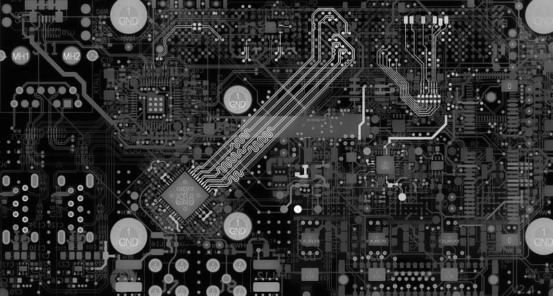
Once the templates were in place, the real work could begin. For those unfamiliar with electronic design, there are three major elements that go into producing the design files required for creating printed circuit boards:
- Individual components
- Schematic
- Layout
In large companies, these tasks are generally performed by three different people. A librarian will create digital representations of the components and manage the company’s parts library, a design engineer will create the schematic, and the CAD (computer aided design) group will combine both of these into a physical representation of what will actually be fabricated.

As the only electrical engineer at Iris, I became intimately familiar with all of these tasks, leveraging my past experiences and observations at larger companies to figure out how to best fill these roles with one mind.
There are some serious advantages and disadvantages to having one person perform all of these tasks.
The greatest advantage is speed. If I need something, I can just do it. I can assume the role of the librarian, design engineer, layout engineer, firmware engineer, test engineer, compliance engineer, component engineer, buyer, and project manager, without having to waste a single minute in meeting rooms conveying information back and forth.
This increase in agility and speed is only a net gain so long as it doesn’t result in a mistake or set back that could have otherwise been avoided by simplifying and compartmentalizing these tasks into specialized individuals or groups. At start-ups, speed is generally favored over avoiding mistakes.
There is also something to be said for having numerous minds to bounce ideas off of and gain perspective when stuck on challenging problems or decisions. This is perhaps the biggest down side to working as a one man team.
“If you want to go fast, go alone. If you want to go far, go together.” — African Proverb
The Balancing Act
Casia needs to not only perform its intended functions, but to do so in a manner that is both efficient and compact, as energy and weight are scarce resources on small aircraft. To achieve this, choosing the right components became a multidimensional balancing act.

Because different drones utilize varying amounts of battery cells connected in series, Casia needed to be able to accept a wide voltage input range which could then be regulated to the six different voltage levels required by all of the peripherals within the module.
This meant that switching regulators had to be used, as their efficiency over a wide input range far outperforms their linear counterparts. This increase in power efficiency comes at the expense of additional components (cost, size, and weight).
The regulators’ switching frequencies would then be fine tuned in simulation to reduce the amount of inductance and capacitance required to operate. In general, higher switching frequencies allow for a smaller inductor and filter capacitors, but this comes at the expense of both increased switching losses and potential electromagnetic interference issues.
There is a saying in economics that, “There is no such thing as a free lunch,” and this is also true in engineering. Every decision comes at a cost and it is up to the designer to spend their design choices wisely.
The next challenge was to accommodate for the immense amount of data being moved into, out of, and within Casia. Cameras produce a lot of data, and this data needs to be moved as quickly as possible into the on-board GPU, as well as being stored in non-volatile memory. To achieve this, Casia utilizes many high speed interfaces, such as MIPI CSI-2, USB 3, GMSL, and SATA to name a few.
Accommodating for circuits at this speed (rise time) isn’t a trivial task, so I turned to some well-known resources such as, “High Speed Digital Design: A Handbook of Black Magic,” by Howard Johnson and Martin Graham.

Additionally, I utilized Iris’ professional development stipend to attend PCB West, a four day conference in Santa Clara with classes focused around high speed design, electromagnetic compatibility, and manufacturing.
Beyond being electrically functional, Casia had to be user friendly and robust. This meant that connectors should be logically placed in such a way that they would be accessible by a human hand once installed on a drone, and that the hardware would contain a redundant microcontroller that would serve as a watchdog over the main processor in the event that it malfunctions.
All of this aforementioned work simply allows for the module to be powered and for data to be moved and operated on. While all of this ground work is necessary, it is yet to make for an interesting and useful product.
What makes Casia interesting is the software and machine learning that brings it to life, allowing it to act on the data it gathers in order to prevent its host from colliding with other aircraft.
After hundreds of hours of focused design effort, I was finally ready to send off all of my files to the contract manufacturer. Completing a PCB design is a lot like packing for a very long and distant trip, you only get one shot and there’s no turning back to grab a forgotten item.

For the software folk, it’s akin to writing code for an entire application and only getting to compile once you’re finished. As you can imagine, attention to detail and relentless foresight is critical. Oh, and it costs thousands of dollars each time you compile.
In the click of a button, the files are sent to the contract manufacturer, and your bank account appears as if you had just purchased a nice used car.
In the coming days, I would serve as a point of contact to address any discrepancies discovered by the contract manufacturer.
Each email or phone call sent my heart racing with fear that I had made a mistake. Majority of these issues were minor, such as ceramic capacitors being out of stock. The lack of supply of ceramic capacitors would become a recurring theme throughout 2018 and early 2019.
One evening, during my commute home from work, I received a phone call that nearly gave me a heart attack. The person on the phone told me that they were having trouble soldering a connector to our boards, and that they suspected the footprint was incorrect. If that wasn’t bad enough, they followed up by saying that they had already soldered the other 428 components onto each of the boards.
I immediately felt nauseous. This was easily the most important component on the board, as it is used to interface to Casia’s main compute module, an NVIDIA Jetson TX2. If this component could not be soldered onto the boards, the entire prototype run would have been a waste.
I rushed home and fired up my computer to begin checking the design files and datasheets. After combing over the connector in question, I convinced myself that I had not made a mistake. The contract manufacturer was closed so I would have to wait until morning to get more information.
After a restless night, I would come to find out that the assembler had the wrong connector and that they would be overnighting the correct one to finish assembly. The confirmation was relieving, but I wouldn’t feel content until I had the boards in hand.
A few days later, still on edge, I received the boards in the mail and the moment of truth commenced.
I carefully cut into the box and began unpacking the boards from their protective ESD packaging. My mind was playing out scenarios where the boards would not power up and I would look like a complete fool.
I reluctantly applied power to the input.
To my delight, I was greeted by the welcoming green glow of the LED whose function is to indicate that power has been applied. This was good. Nothing was on fire, nothing was hot to the touch.
I began probing test points with a multimeter and read the correct voltages on each of the six voltage regulators’ outputs. The current draw from the power supply seemed reasonable based on my power calculations. It was now safe to begin testing the numerous sub-circuits with Casia.
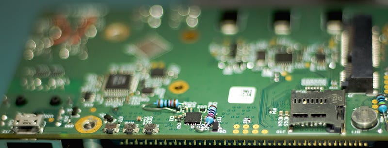
I flashed some test firmware that I had written onto the microcontroller that is responsible for booting up the Jetson TX2. I then connected the TX2 to the 400 pin connector on the carrier board. Its alignment with the stand-offs and mounting holes was perfect.
I reapplied power and noticed that the current draw from the power supply had increased. The TX2 was active and was drawing power. I plugged in an Ethernet cable and anxiously waited for a new IP address to appear on the local network. I SSH’d into the newfound device and was greeted by the Linux terminal. A feeling of relief swept over me.
Over the coming weeks, I would go on to perform a laundry list of checks and tests on Casia’s interfaces and peripherals. Mistakes were made on the first prototype, but nothing an X-ACTO knife, 30 gauge wire, and some out of place resistors couldn’t fix.

I reworked the hardware into a state where I was comfortable putting it on a drone for field testing, where it would be flown against a Cessna 172 — Iris Automation has a Flight Operations team consisting of both remote and commercial pilots who fly drones against manned aircraft regularly in order to collect data and prove out our technology.
The field testing on the first prototype couldn’t have gone better. Casia was communicating with the autopilot, and its camera was capturing data and storing it to its solid state hard drive.

At this point, the lessons learned could be wrapped into a second revision, and passing compliance testing would be my next focus before proceeding with a production run.
If you found this story interesting, stay tuned for part two where I will share my experience with compliance testing, our first major production run, feedback from AUVSI XPONENTIAL 2019, and my feelings surrounding our first official customer sale!
